Business Articles - Specialty and Trade
Articles & Tips
Make sure the wall is strong enough to resist the lateral pressure of the soil
Concrete basement walls are designed to do two main jobs. One job is supporting the house; the other is holding back the pressure of soil against the side of the basement.
Considering the nature of concrete, holding up the weight of the house is the lesser worry. Concrete’s compressive strength is much greater than it needs to be to support a house. As long as the soil under the footing has adequate bearing capacity, the ability of a concrete wall to carry the load is not a question.
Soil pressure against the basement walls, on the other hand, can sometimes be a problem. A sideways force against a basement wall puts one face of the wall in tension (see Figure 1, next page), and concrete’s tensile strength is much lower than its compressive strength. Designing a wall to prevent failure in bending requires a proper analysis of the soil loads and an appropriate structural design of the wall. It’s important to consider not just the wall’s construction, but also the drainage provided and the way the wall is tied to the house’s floor frame.
Lateral Soil Pressure
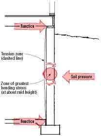
| Figure 1. The amount of pressure applied by the soil varies: It depends on the type of soil, the drainage conditions, and the depth of the backfill. Silt typically applies 50% more pressure than sand or gravel; and clays, when saturated with water, can apply two or three times the pressure of sand or gravel. |
In any type of soil, lateral soil pressure increases with depth, so tall walls get more pressure than short walls. Under identical soil conditions, the load experienced by a 9-foot basement is around 50% greater than the load felt by an 8-foot basement. A 10-foot basement feels almost double the load felt by an 8-foot basement in the same type of soil (Figure 2).
Taking both conditions together — a taller wall, plus a “heavier” soil — the effects can be severe. For example, a 10-foot basement wall backfilled with a moderately soft clay soil in an undrained condition feels a load of 4,000-plus pounds per foot — close to four times the approximately 1,250 pounds per foot of wall experienced by an 8-foot basement backfilled with sand or gravel. To handle the load, the taller wall in the heavier soil will require a much stouter design.
So the ability of a tall basement wall to hold up against soil pressures, especially in poorly drained silt or clay soil, is not something you can take for granted. It’s important to identify the soil type on site, to assess the pressure the specific soil will apply to a wall of the height you’re building, and to design the wall accordingly. Many block or treated wood basements, and even some concrete basements, have failed when assumed soil pressures typical of sand or gravel were used for the design but actual soil conditions involved a poorly drained silt or clay backfill.
Load Comparison: Soil Type and Wall Height
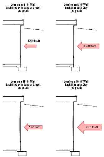
| Figure 2. Soil type and backfill height both affect the lateral pressure on a basement wall. Backfilling with a clay soil instead of sand can increase the load by double or more, while going from an 8-foot to a 10-foot wall, just a 25% height increase, adds 50% to the lateral pressure. Taller walls backfilled with heavier soil risk failure unless correct design methods are followed. |
Soil Type, Drainage & Pressure
Soil can be the hardest material in all of construction to define. Even on a single site, soil is seldom uniform in particle size, density, mineral makeup, or moisture content. And it’s very hard to identify soils by eye: A shovelful of soil that seems to have a lot of sand and gravel in it could well contain 30% clay or more. If so, it would behave like clay, not sand with regard to bearing capacity, drainability, and lateral pressure of soil.
Computers have helped us refine our computations about soil mechanics, but analyzing soil loads still involves a lot of uncertainty. The theories and formulas we use are typically just general approximations. Uncertainty about soil loading is one reason engineers usually employ significant factors of safety in foundation design.
But knowledge and understanding of soil can help put lateral earth pressure in proper perspective. Soils can be identified, and, once identified, their properties can be predicted with reasonable confidence. This provides a basis for safe and economical design decisions.
Also, because dry soil exerts less pressure than wet soil, the lateral pressure of soil can be reduced by providing a good foundation drainage system. This enables an experienced designer to use a less conservative factor of safety in the design of the wall structure, as long as good quality control on site ensures that the proper drainage details are reliably put in place.
Categorizing soils. In the U.S., most engineers and construction companies use the Unified Soil Classification System to identify and categorize soils (see Table 1 for a condensed version). If you have lab testing done on a soil sample, the report will probably use these soil type classifications.
For our purposes, I’ve simplified the picture by grouping the various soil types into five main classes, based on approximate values for the lateral pressure of soil (Table 2, page 5). (These classes aren’t the same as the “groups” given in Table 1.) If you can be confident about which class your site soils fall into, you can estimate the lateral pressure of soil on your wall and build the wall accordingly. Don’t guess, however: Unless you have reliable data on the soil from a soil engineer’s site report or a laboratory soil test, assume a load condition typical of clay, not sand.
Properties of Soils According to the Unified Soil Classification System
|
Soil Group |
Unified Soil |
Soil Description |
Drainage |
Frost |
Volume |
|
Group I |
GW |
Well-graded gravels, gravel-sand |
Good |
Low |
Low |
|
GP |
Poorly graded gravels or gravel- |
Good |
Low |
Low |
|
|
SW |
Well-graded sands, gravelly sands, |
Good |
Low |
Low |
|
|
SP |
Poorly graded sands or |
Good |
Low |
Low |
|
|
GM |
Silty gravels, gravel-sand mixtures |
Good |
Medium |
Low |
|
|
SM |
Silty sand, sand-silt mixtures |
Good |
Medium |
Low |
|
|
Group II |
GC |
Clayey gravels, gravel-sand-clay mixtures |
Medium |
Medium |
Low |
|
SC |
Clayey sands, sand-clay mixtures |
Medium |
Medium |
Low |
|
|
ML |
Inorganic silts and very fine sands, |
Medium |
High |
Low |
|
|
CL |
Inorganic clays of low to medium |
Medium |
Medium |
Medium to Low |
|
|
Group III |
CH |
Inorganic clays of high plasticity, fat clays |
Poor |
Medium |
High |
|
MH |
Inorganic silts, micaceous or diatomaceous |
Poor |
High |
High |
|
|
Group IV |
OL |
Organic silts and organic |
Poor |
Medium |
Medium |
|
OH |
Organic clays of medium to |
Unsatisfactory |
Medium |
High |
|
|
Pt |
Peat and other highly organic soils |
Unsatisfactory |
Medium |
High |
|
The percolation rate for good drainage is over four inches per hour, medium drainage is two to four inches per hour, and poor is less than two inches per hour. |
| Table 1. The table above shows the two-letter designations for the soil types defined in the Unified Soil Classification System, which is widely used for construction engineering. A soil engineering report will usually use this scheme to identify soils on a site. In general, sands and gravels have good characteristics for bearing strength and drainage, while soils that contain more fine silt or clay are weaker and drain more slowly. Soils that contain large amounts of decaying plant material (the peats and organic clays) are no good for building and have to be removed. |
Soil pressure is given in the form of “equivalent fluid pressure.” This is based on the understanding that soil pressure, like water pressure, increases with depth. Just as water pressure on a submarine deep in the ocean is greater than water pressure on that submarine at the surface, and just as the pressure of wet concrete is greatest at the bottom of the forms, soil pressure is found to be greater at the bottom of a basement wall than at the top. When we estimate the total load on a wall from lateral soil pressure, we total up the accumulated pressures at every depth and express that as a single number. The greater the equivalent fluid pressure of the soil type, and the greater the backfill height (wall depth), the greater this total load will be.
The values I’ve provided for equivalent fluid pressure in each soil class assume that the builder has provided continuous exterior footing drains with a gravel cover. Builders in some parts of the country, however, are still installing drains on the interior of footings under the basement floor, instead of outside the footings, even though that violates code in most localities. If you use an interior rather than an exterior footing drain, the drainage won’t be as effective, and the soil may sit in an undrained condition and exert higher pressures. So without exterior footing drains, the wall design should use the soil pressure of the next higher class: that is, 45 pcf/ft in a sand soil, 60 pcf/ft in a silt soil, and so on. I’ve seen many basement wall failures in masonry block foundations equipped with interior rather than exterior footing drain systems.
Design Lateral Soil Load
|
Class I |
Class II |
Class III |
Class IV |
Class V |
|
30 pcf/ft |
45 pcf/ft |
60 pcf/ft |
75 pcf/ft |
90 pcf/ft |
|
GP, GW, SW, SP, GM |
GC, SK, SC, SM-SC |
ML, CL, ML-CL |
OL |
OH, CH, MH |
| Table 2. For purposes of basement wall design, the author has created this simple grouping of soil types from the Unified Soil Classification System. Each class has a typical "equivalent fluid pressure" that is used to estimate the total lateral pressure of soil on a basement wall. The coarse, granular sands and gravels in Class I exert the least pressure, while increasingly finer and more plastic soils fall into higher and higher classes and are assumed to apply a greater load. The clays and silts with high plasticity (grouped in Class V) apply the greatest lateral pressure; walls in such soils need to be very thick or contain large amounts of reinforcing steel. Effective drainage can help to reduce the in-service load applied by all types of soil. |
Building Strong Walls
A concrete wall’s strength depends on the quality of the concrete, the thickness of the wall, and the presence or absence of steel reinforcement. When soil conditions place a higher load on the wall, you don’t necessarily have to add steel to the wall; instead, using the plain concrete design method described on page 7, you can increase a wall’s strength by thickening the wall, using a stronger concrete mix, or both.
For the highest loads, you’re sometimes going to need steel; but up to a certain point, the choice between plain concrete and reinforced concrete is a practical one — either option could be more economical, depending on your local costs for concrete, steel, and labor. But whether you choose to spend your budget on concrete (pouring a thicker wall) or on steel and labor time (having the crew place and tie rebar), it’s important to match the solution to realistic load assumptions.
The ACI 318 Code. Concrete structural design rules are found in Building Code Requirements for Structural Concrete (ACI 318), an American Concrete Institute document that is revised periodically to reflect advances in technology and understanding.
Ultimate strength method. Table 3 for steel-reinforced walls is drawn directly from the “ultimate strength” method long established in ACI 318. The taller the wall and the greater the assumed soil pressure, the more steel that’s needed. The on-center dimensions given here are for both vertical and horizontal steel. For this table, I have assumed a concrete compressive strength of at least 3,000 psi (28-day value), but the concrete strength is less of a structural issue when steel reinforcement provides the necessary tensile strength on the tension face of the wall.
Steel Requirements for Walls in Various Soil Conditions
Designed According to the ACI 318 Ultimate Strength Method
|
Soil Type |
Sand |
Silt |
Clay |
Wet Silt or Clay |
Fat Clay |
|
Equivalent Fluid Pressure (f) |
f = 30 pcf/ft |
f = 45 pcf/ft |
f = 60 pcf/ft |
f = 75 pcf/ft |
f = 90 pcf/ft |
|
Steel Requirement |
|||||
|
8-inch wall, 8'0" high with 7'4" of backfill |
#4 bar at 48" O.C. |
#4 bar at 36" O.C. |
#4 bar at 24" O.C. |
#4 bar at 24" O.C. |
#4 bar at 18" O.C. |
|
8-inch wall, 9'0" high with 8'4" of backfill |
#4 bar at 36" O.C. |
#4 bar at 24" O.C. |
#4 bar at 18" O.C. |
#4 bar at 16" O.C. |
#4 bar at 12" O.C. |
|
8-inch wall, 10'0" high |
#4 bar at 24" O.C. |
#4 bar at 16" O.C. |
#4 bar at 12" O.C. |
#5 bar at 16" O.C. |
#5 bar at 12" O.C. |
| Table 3. The table above shows steel requirements for concrete walls built in soils of various equivalent fluid pressures at various heights, based on the "ultimate strength" method found in the American Concrete Institute’s ACI 318 Code. The taller the wall and the greater the soil pressure, the greater the amount of steel that's called for. This chart assumes an 8-inch wall thickness. In all cases, a 3,000-psi concrete mix should be used. |
Plain concrete method. The latest version of the 318 Code, ACI 318-99, contains a new Chapter 22, which explains the “plain concrete” method used to design unreinforced walls. Under that method, the greater the assumed soil pressure or the taller the wall, the thicker the wall must be. Increasing the compressive strength of the concrete also improves the wall’s capacity to handle lateral soil pressures, because concrete’s tensile strength, while low, increases when the compressive strength is increased. In Tables 4a and 4b (previous page), I have applied the Chapter 22 method to arrive at required wall thicknesses for walls of 8-foot, 9-foot, and 10-foot heights in a range of soil classes. I’ve included only three compressive strengths (2,500 psi, 3,500 psi, and 4,500 psi), but it’s possible to get greater wall strengths by using stronger mixes, thus perhaps allowing use of a thinner wall.
Walls designed with the plain concrete method are unreinforced walls; the only rebar I generally call for in those walls is two horizontal #4 (halfinch) bars near the top and one horizontal #4 bar near the bottom for crack control. (It can also be helpful to place rebar near window and door openings and behind beam pockets, but that’s a subject for another article.)
Table 4a is derived from applying the Chapter 22 methods by the book. Table 4b is based on my own experience and knowledge in wall design and construction, and represents what I consider an appropriate modification of the factor-of-safety to reflect the effect of careful attention to drainage and bracing details. As you can see, under some soil conditions, Table 4b would allow a thinner wall than Table 4a.
Examples of Plain Concrete Basement Walls Backfilled With
Various Soil Types
Table 4a
(Assumes continuous exterior footing drain tile with gravel
cover and approved wall-to-sill connection)
|
Soil Type |
Sand |
Silt |
Clay |
Wet Silt or Clay |
Fat Clay |
|
Equivalent Fluid Pressure (f) |
f = 30 pcf/ft |
f = 45 pcf/ft |
f = 60 pcf/ft |
f = 75 pcf/ft |
f= 90 pcf/ft |
|
Minimum Wall Thickness (2500 psi concrete) |
|||||
|
(Wall 8'0" high with 7'4" of backfill) |
8 inches |
10 inches |
10 inches |
12 inches |
12 inches |
|
(Wall 9'0" high with 8'4" of backfill) |
10 inches |
12 inches |
12 inches |
engineering required |
engineering required |
|
(Wall 10'0" high with 9'4" of backfill) |
10 inches |
12 inches |
engineering required |
engineering required |
engineering required |
|
Minimum Wall Thickness (3500 psi concrete) |
|||||
|
(Wall 8'0" high with 7'4" of backfill) |
8 inches |
8 inches |
10 inches |
10 inches |
12 inches |
|
(Wall 9'0" high with 8'4" of backfill) |
8 inches |
10 inches |
12 inches |
12 inches |
engineering required |
|
(Wall 10'0" high with 9'4" of backfill) |
10 inches |
12 inches |
engineering required |
engineering required |
engineering required |
|
Minimum Wall Thickness (4500 psi concrete) |
|||||
|
(Wall 8'0" high with 7'4" of backfill) |
6 inches |
8 inches |
10 inches |
10 inches |
engineering required |
|
(Wall 9'0" high with 8'4" of backfill) |
8 inches |
10 inches |
12 inches |
12 inches |
engineering required |
|
(Wall 10'0" high with 9'4" of backfill) |
10 inches |
12 inches |
engineering required |
engineering required |
engineering required |
Table 4b
(Assumes continuous exterior footing drain tile with gravel cover,
approved wall-to-sill connection, and dimpled-sheet drainage
membrane attached to foundation wall for enhanced soil drainage)
|
Soil Type |
Sand |
Silt |
Clay |
Wet Silt or Clay |
Fat Clay |
|
Equivalent Fluid Pressure (f) |
f = 30 pcf/ft |
f = 45 pcf/ft |
f = 60 pcf/ft |
f = 75 pcf/ft |
f = 90 pcf/ft |
|
Minimum Wall Thickness (2500 psi concrete) |
|||||
|
(Wall 8'0" high with 7'4" of backfill) |
6 inches |
8 inches |
10 inches |
10 inches |
10 inches |
|
(Wall 9'0" high with 8'4" of backfill) |
8 inches |
10 inches |
10 inches |
12 inches |
engineering required |
|
(Wall 10'0" high with 9'4" of backfill) |
10 inches |
12 inches |
12 inches |
engineering required |
engineering required |
|
Minimum Wall Thickness (3500 psi concrete) |
|||||
|
(Wall 8'0" high with 7'4" of backfill) |
6 inches |
8 inches |
8 inches |
10 inches |
10 inches |
|
(Wall 9'0" high with 8'4" of backfill) |
8 inches |
8 inches |
10 inches |
12 inches |
12 inches |
|
(Wall 10'0" high with 9'4" of backfill) |
8 inches |
10 inches |
12 inches |
engineering required |
engineering required |
|
Minimum Wall Thickness (4500 psi concrete) |
|||||
|
(Wall 8'0" high with 7'4" of backfill) |
6 inches |
8 inches |
8 inches |
10 inches |
10 inches |
|
(Wall 9'0" high with 8'4" of backfill) |
8 inches |
8 inches |
10 inches |
10 inches |
12 inches |
|
(Wall 10'0" high with 9'4" of backfill) |
8 inches |
10 inches |
12 inches |
12 inches |
engineering required |
| Table 4. The tables above show the results of applying the plain concrete design method from ACI 318-99 for a variety of wall heights and soil conditions. Using a backfill material with a higher equivalent fluid pressure, or increasing the wall height and backfill depth, increases the load on the wall. Increasing the strength of the concrete mix or the thickness of the wall increases the wall’s capacity. So taller walls in heavier soils should be made thicker or with stronger concrete. Table 4a is based directly on the ACI method, but for Table 4b, the author has applied a reduced "strength reduction factor," a factor of safety. The author considers this reduced factor of safety to be appropriate for residential work if a dimpled-sheet drainage membrane is applied to the foundation wall to ensure a drained condition in the backfill soil. Table 4b is provided for illustration only; an engineer should be consulted for specific projects. |
In my opinion, Chapter 22 should be revised again to allow for a less conservative wall structure when drainage and bracing are properly addressed, as in Table 4b. I believe that historical experience with actual walls in service indicates that this would be an appropriate change. But it has yet to be made, so bear in mind that Table 4b is only one engineer’s opinion. You should apply a similar approach on your own jobs only with the advice and approval of the designer or engineer responsible for a particular job.
Soil Pressure Loads in Perspective
As building development continues, the “good” building sites are being used up. More and more, we have to put houses on marginal land. Low-lying property near water is likely to have soft, poorly draining soil, and urban properties that have been used before may have been filled in with unsuitable material. Any time you’re not sure of the soil type, getting a soil boring or an engineer’s site report is good insurance.
Most structural wall failures occur during construction, because of careless backfilling without proper wall bracing. In service, most wall failures happen because of the gradual consolidation of saturated fine soil, resulting in excessive soil loading after many years of increasing pressure.
Fine soils in particular exert lower pressures when in a drained condition. So good surface drainage and proper footing drains around the entire perimeter are the most important features for watertight and structurally sound basement walls. Dimpled-sheet drainage membranes provide the best drainage and will allow most soil types to be used safely for backfill, because the soil can be kept in the drained condition.
Bracing the foundation walls against backfilling loads is the second most important factor. It’s best to tie the floor frame to the foundation before backfilling; otherwise, a solid wall brace every 15 feet or so is recommended.
Wall design has to match the wall structure to the lateral loads of soil. But if the bracing and drainage procedures I’ve described are followed, the soil loading creates less of a risk. The wall design can take that reduced risk into account. The result will be a wall that performs well in service, at a more affordable cost.
Brent Anderson is a professional engineer and concrete consultant. His Minneapolis-area company provides concrete construction, investigation, and repair services.
This article has been provided by www.jlconline.com. JLC-Online is produced by the editors and publishers of The Journal of Light Construction, a monthly magazine serving residential and light-commercial builders, remodelers, designers, and other trade professionals.
Join our Network
Connect with customers looking to do your most profitable projects in the areas you like to work.